Posts

Use PCM5102 with STM32

Image
Use PCM5102 with STM32 PCM5102 and STM32 Here are my tiny notes about the connection of PCM5102 DAC to STM32F401 Nucleo board. I2S interface requires three wires to work: SCK is officially called as “continuous serial clock (SCK)”, but also you can found “bit clock” name. It is just the same clock as usual in the SPI interface. Word Select clock is used to select, which cannel is active now, 0 for left channel, 1 for right. It also called called “left-right clock (LRCLK)” or “frame sync (FS)”. Serial data - actual data. CubeMX settings Wiring diagram My board has such pins: | 3.3V | 3.3V on Nucleo board | | FLT | Filter select, grounded: select normal latency, grounded | | DMP | De-emphasis control, grounded(OFF) | | SCL | System clock input, in datasheet SCK pin. System clock is internally generated, it should not be wired anywhere | | BCK | Audio data bit clock input. In I2S terminology is equivalent to serial clock(SCK) I've connected i

RFFT in CMSIS DSP. Part 1.

Image
RFFT in CMSIS DSP. Part 1. RFFT in STM32 using CMSIS DSP. Part 1. Python warm-up for illustration I always wanted to use MCU for audio processing. And for my purposes, I need Discrete Fourier Transform(DFT), especially its fast version FFT. If you do not know what is this, read Wikipedia first:) FFT has a huge number examples of usage, for my case I want to build wavetable synthesizer. Let’s take some real example. We have an audio signal, which is just a set of amplitudes, which you will take from your ADC. Samples are taken with some sampling frequency Fs. For preliminary illustration, we’ll use Python. import numpy as np import matplotlib . pyplot as plt # Our wave settings N_samples = 32 amplitude = 10 # Here we'll generate our sine wave t = np . arange ( N_samples ) x = amplitude * np . sin ( 2 * np . pi * t / N_samples ) # Plotting fig , ax = plt . subplots ( ) ax . plot ( t , x , 'bo-' ) ax . set_xlabel ( 'N sa

u8g2 library usage with STM32 MCU

Image
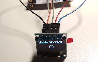
Several years ago I wrote couple of articles about beautiful library u8glib in context of STM32 microcontrollers. Time moves on and author of this library released newer one, u8g2. u8glib is officially deprecated and not developed anymore. We cannot afford to lose code support for our libraries, time to move to newer library! Differences between these libraries are listed there, also there are a lot of helpful information about u8g2 library. It is not so hard to modify your old u8glib code for newer library. I'll show you how to use this library with Nucleo-F401 board and SSD1306 display, bought on Aliexpress. Display connection is SPI, pins are GND, VCC, SCL(the same as SPI clock), SDA(the same as MOSI), RES and DC. Wiring is: PA5 -> SCL PA7 -> SDA PA9 -> OLED_RES PC7 -> OLED_DC I use CubeMX code generation tool to initialize all the peripheral.  OLED_RES and OLED_DC is just GPIO output. SPI1 initialized with default parameters. u8g2 library has it

Elastic Notes: CubeMX under linux in couple with System Workbench...

Elastic Notes: CubeMX under linux in couple with System Workbench... : Yes, it really happened! During update of CubeMX, I've glanced on list of changes, and not believed to my eyes: ST released linux ver...

Elastic Notes: STM32 + SPI OLED SSD1306 + u8glib + CubeMX

Elastic Notes: STM32 + SPI OLED SSD1306 + u8glib + CubeMX : As I promised, I post info about connection SPI-based display based on SSD1306 controller using STM32 CubeMX. Its connection is even simple...

Elastic Notes: STM32 + I2C OLED SSD1306 + u8glib + CubeMX

Elastic Notes: STM32 + I2C OLED SSD1306 + u8glib + CubeMX : If you think, that title of this post consists of all possible random words, you are wrong:) This is what I've try to chain right during couple of days, but it was not so simple, as I thought at first time!

Elastic Notes: CubeMX - STM32 encoder interface

Elastic Notes: CubeMX - STM32 encoder interface : Couple a days ago, I've got struck with connection of encoder to my stm32 board. But,    the answer to the puzzle was quite simple:) So,...