Use PCM5102 with STM32
PCM5102 and STM32

Here are my tiny notes about the connection of PCM5102 DAC to STM32F401 Nucleo board.
I2S interface requires three wires to work:
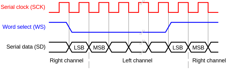
- SCK is officially called as “continuous serial clock (SCK)”, but also you can found “bit clock” name. It is just the same clock as usual in the SPI interface.
- Word Select clock is used to select, which cannel is active now, 0 for left channel, 1 for right. It also called called “left-right clock (LRCLK)” or “frame sync (FS)”.
- Serial data - actual data.
CubeMX settings

Wiring diagram
My board has such pins:
| 3.3V | 3.3V on Nucleo board  |
| FLT  | Filter select, grounded: select normal latency, grounded  |
| DMP  | De-emphasis control, grounded(OFF)  |
| SCL  | System clock input, in datasheet SCK pin. System clock is internally generated, it should not be wired anywhere  |
| BCK  | Audio data bit clock input. In I2S terminology is equivalent to serial clock(SCK) I've connected it to `PB10 > I2S2_CK` |
| DIN  | Audio data input. This is Serial Data pin, I've connected it to `PC3 > I2S2_SD` |
| LCK  | Is LRCK in PCM5102 datasheet, which is Audio data word clock input. It is used to switch data for left and right channel. In I2S is I2SX_WS pin, means "Word Select" pin. Connect it to `PB12 > I2S2_WS` |
| FMT  | Audio Format Selection, we select I2S, so this should be grounded  |
| XMT  | In dataseet is XSMT, which is mute control, should be HIGH to unmute.  |
As we see, only three wires used for actual data transmission, others are miscellaneous.
Test code
Actual test code is quite simple, here we just put triangle wave to I2S via HAL_I2S_Transmit function.
const uint16_t triangle_wave[]  = {
0x400,0x800,0xc00,0x1000,0x1400,0x1800,0x1c00,0x2000,
0x2400,0x2800,0x2c00,0x3000,0x3400,0x3800,0x3c00,0x4000,
0x4400,0x4800,0x4c00,0x5000,0x5400,0x5800,0x5c00,0x6000,
0x6400,0x6800,0x6c00,0x7000,0x7400,0x7800,0x7c00,0x8000,
0x83ff,0x87ff,0x8bff,0x8fff,0x93ff,0x97ff,0x9bff,0x9fff,
0xa3ff,0xa7ff,0xabff,0xafff,0xb3ff,0xb7ff,0xbbff,0xbfff,
0xc3ff,0xc7ff,0xcbff,0xcfff,0xd3ff,0xd7ff,0xdbff,0xdfff,
0xe3ff,0xe7ff,0xebff,0xefff,0xf3ff,0xf7ff,0xfbff,0xffff,
0xfbff,0xf7ff,0xf3ff,0xefff,0xebff,0xe7ff,0xe3ff,0xdfff,
0xdbff,0xd7ff,0xd3ff,0xcfff,0xcbff,0xc7ff,0xc3ff,0xbfff,
0xbbff,0xb7ff,0xb3ff,0xafff,0xabff,0xa7ff,0xa3ff,0x9fff,
0x9bff,0x97ff,0x93ff,0x8fff,0x8bff,0x87ff,0x83ff,0x8000,
0x7c00,0x7800,0x7400,0x7000,0x6c00,0x6800,0x6400,0x6000,
0x5c00,0x5800,0x5400,0x5000,0x4c00,0x4800,0x4400,0x4000,
0x3c00,0x3800,0x3400,0x3000,0x2c00,0x2800,0x2400,0x2000,
0x1c00,0x1800,0x1400,0x1000,0xc00,0x800,0x400,0x0,
};

int main(void)
{
  HAL_Init();
  SystemClock_Config();
  MX_GPIO_Init();
  MX_I2S2_Init();
  MX_USART2_UART_Init();
  while (1)
  {

    /* Here is our actual code */
    HAL_I2S_Transmit(&hi2s2, triangle_wave, sizeof(triangle_wave)/sizeof(triangle_wave[0]), 1000);
  }
}
That is all, you should hear triangle wave in connected to PCM5102 module.

Sorry, but the image is really small to get the CubeMX settings. Why not to post the complete project files?
ReplyDeleteCode generator outputs:
ReplyDeletehi2s2.Instance = SPI2;
hi2s2.Init.Mode = I2S_MODE_MASTER_TX;
hi2s2.Init.Standard = I2S_STANDARD_PHILIPS;
hi2s2.Init.DataFormat = I2S_DATAFORMAT_16B_EXTENDED;
hi2s2.Init.MCLKOutput = I2S_MCLKOUTPUT_DISABLE;
hi2s2.Init.AudioFreq = I2S_AUDIOFREQ_32K;
hi2s2.Init.CPOL = I2S_CPOL_LOW;
hi2s2.Init.ClockSource = I2S_CLOCK_PLL;
hi2s2.Init.FullDuplexMode = I2S_FULLDUPLEXMODE_DISABLE;
Little update: looks like SCL pin should be connected to ground, not be floating...
ReplyDeleteThe resolution of the image showing the CubeMX settings is way too low. Unreadable!
ReplyDeleteI'm also disappointed about the bad screenshot quality. And could you comment on post:
ReplyDelete" looks like SCL pin should be connected to ground, not be floating..."
The data should be ordered for stereo transmision, so doubled, like:
ReplyDeleteconst uint16_t triangle_wave[] = {
0x400,0x400, 0x800,0x800, 0xc00,0xc00,0x1000,0x1000,0x1400,0x1400, etc..